
A Comparison of Scan to BIM Workflows: Photogrammetry or LIDAR?
When it comes to capturing the existing conditions of your assets, the two main approaches that matter are lidar and photogrammetry.
Singapore has seen a rise in demand for scan to BIM workflows among project owners. One reason for this is that most alteration and addition (A&A) works above 5000sqm require BIM submissions to the relevant authorities.
While it can be prohibitively expensive to recreate an existing asset in BIM, scanning has become a more cost and time-effective option of doing so. Scan to BIM has become an increasingly popular solution for accurately capturing and modeling existing structures, systems, and elements in a digital format.
By understanding the scan to BIM workflow and its understand key terminologies, we hope to facilitate more productive conversations with scan to bim companies.
Which Method Should I Choose for Scan to BIM: LIDAR or Photogrammetry?
| Feature | LiDAR | Photogrammetry |
|---|---|---|
| Technology | Uses laser pulses to measure distances | Uses photographs to create 3D models |
| Accuracy | High accuracy, especially in capturing detailed geometries | Moderate accuracy, dependent on the quality and number of images |
| Data Output | Point cloud data | 3D models, point clouds, and textured surfaces |
| Environmental Conditions | Performs well in various conditions, including low light | Requires good lighting conditions for high-quality images |
| Cost | Generally higher cost due to specialized equipment | Lower cost, using standard cameras and drones |
| Processing Time | Faster processing time for data collection | Longer processing time due to the need to process multiple images |
| Use Cases | Topographic mapping, forestry, infrastructure, and construction | Architectural surveys, cultural heritage, and smaller-scale mapping |
| Vegetation Penetration | Can penetrate through vegetation to capture ground details | Limited ability to capture ground details under dense vegetation |
The two data capture methods for producing a scan are either LIDAR and Photogrammetry. LIDAR produces data in a point-cloud format (i.e. e.57, .laz, .ptx) while photogrammetry produces data in the form of mesh models (i.e. .obj, . stl, .3mx, . rcp).
With the wide variety of high-definition cameras available today, engineering companies have more options for mounting cameras onto drones. This enables them to quickly and efficiently capture site conditions using drone technology. On the other hand, the option to mount LIDAR cameras to drones are much more limited and less cost-effective.
Generally, as-built conditions captured using LIDAR are more accurate than those captured through photogrammetry, although LIDAR tends to be a more time-consuming approach.
Why Do Engineering Firms Scan Their Existing Assets?
Some of the top use-cases for incorporating scan to BIM include:
- Obtaining a snapshot of existing site conditions
- Recreate missing design documentation
- Verifying the as-built condition against the design BIM
- Digital Twin Visualization
For most engineering applications, point-cloud produced from LIDAR is the preferred mode of data capture. This is because of the precise measurements that can be produced from LIDAR scanners that cannot be matched by conventional cameras.
When the need for precise measurements are not as critical, producing a mesh model from photogrammetry can be a viable option. For example, if you want to showcase a large project site to stakeholders, then the speed of producing a mesh model can be valuable.
An Overview of the Scan to BIM Workflow
Step 1: What is your Use Case?
The business case for Scan to BIM affects how data is captured, processed, and presented. When precision is paramount, LIDAR is the best choice. However, for creating visual models for presentations, photogrammetry, whether using drones or not, is preferred due to its lighter weight.
Step 2: Data Capture
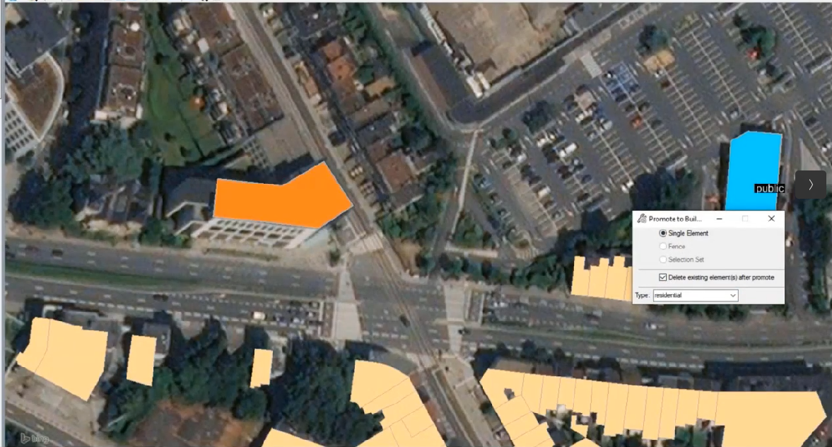
When BIM is used for maintenance workflows, a control survey should be established. With a control survey, the final output is geo-referenced accurately. This is particularly useful when the BIM model needs to be positioned accurately in a GIS application.
During this phase, providing available design files can be helpful to surveyors. It helps them have a better sense of the space to create a site capture plan. With a site capture plan, surveyors can segment the point cloud during the capture phase to prevent the final output from becoming too large. They can also better plan the control points for the site to aid in producing an accurately georeferenced BIM model.
Step 3: Data Processing
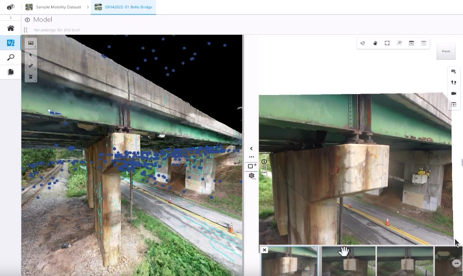
The captured data is imported into specialized software, which registers the point cloud data to the building's coordinate system. This process involves aligning the point cloud data with a survey or control point to provide accuracy. Unnecessary data points are cleaned to facilitate the creation of the BIM or mesh model.
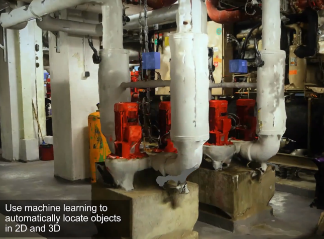
BIM modelling is helpful in this phase as hard-to-reach elements (i.e. Mechanical, Electrical, Piping) may not be fully captured in the scan. These elements may need to be manually created.
Step 4: Review and Insights
As-Built Verification with Scan to BIM
The design model from the client is cross-checked with the point cloud scan. A clash report is produced, and where necessary, the design model will be updated to reflect the as-built condition of the asset.
Typically an L.O.D 300 BIM model will be produced as the final deliverable. However, clients can request for a more detailed BIM model with 5D, 6D, and even 7D attributes.
Visualizing Your Assets with a Mesh Model
In some scenarios, a mesh model (with less defined edges) are sufficient. Precise measurements can be obtained from a mesh, and it can be seamlessly integrated with existing design models. There are a number of free viewers that can be used to check the mesh model for issues.
Permitting Considerations for Scan to BIM Workflows
Certain areas may have specific regulations or flight restrictions that drone operators need to be aware of before planning their flights. For instance, obtaining special permissions or clearance may be necessary to access restricted areas such as Jurong Island. Furthermore, flight altitude may be restricted to a maximum of 60m during weekdays in such areas.
In addition, drone flights must typically maintain a minimum clearance of 15m from the tallest structures. This requirement may require planning flights for weekends when flight restrictions are not limited to 60m.
Also, certain facilities or locations may have specific regulations or requirements that drone operators must adhere to before conducting drone flights. This may include obtaining special permissions or clearances to permit overhead flying and capture of footage.
To ensure safe and legal operations, drone operators should conduct thorough research and carefully comply with all relevant regulations and restrictions, and obtain any necessary permissions or clearances before conducting drone flights in restricted areas.
Conclusion
Scan to BIM is becoming the preferred method of data capture for engineering teams due to its efficiency, accuracy, and cost-effectiveness. In our case, it is now an integral part of our BIM delivery workflow.
Frequently Asked Questions
| Frequently Asked Questions | Answer |
|---|---|
| Which is cheaper, drone or terrestrial scanning | Drones are a more cost-effective option when the area to be scanned is large |
| How can I view the final point cloud? | Bentley Viewer is a free software you can use to view point clouds. |
| How long does it take to generate the final point-cloud | 1-3 working days |
| Can we get structural dimensions from the Point Cloud | Yes |
| What is the difference between a point cloud and a mesh model | A mesh model is a 3D representation of an object made up of interconnected polygons, while a point cloud is a collection of individual points that represent the surface of an object or environment. |
| When should I use a mesh model over a point cloud? | For Scan-to-BIM, simulations, inspections, and surveying use-cases a mesh model is preferred. Visually, the 3D textures generated by a mesh model is more visually appealing, and is able to load much faster in simulation/modelling software due to its smaller size. For engineering, industrial design use-cases (where precise measurements are required), a terrestrial LIDAR scanner due to its precision. |